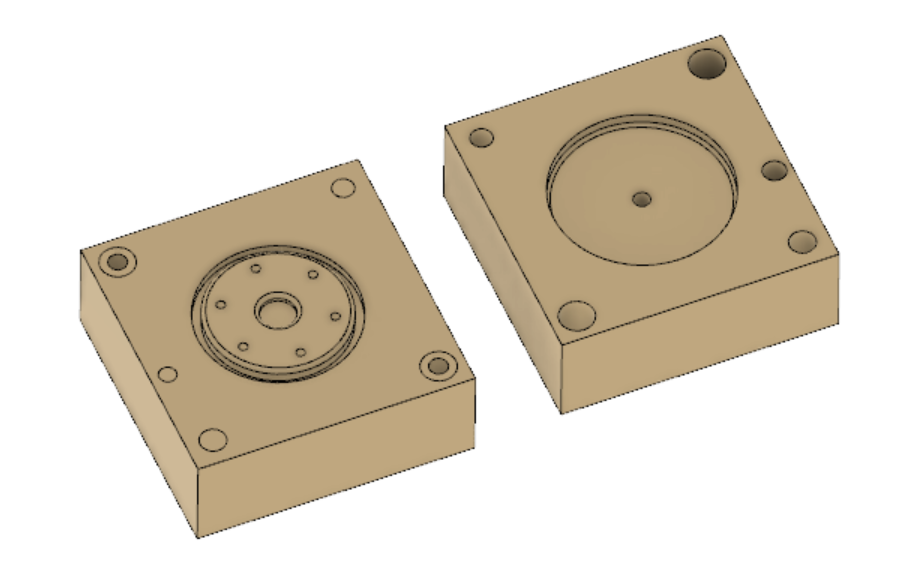
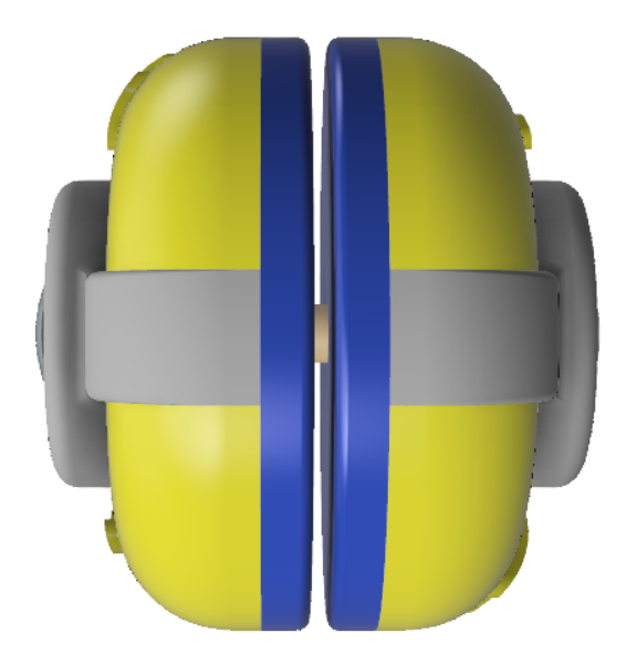
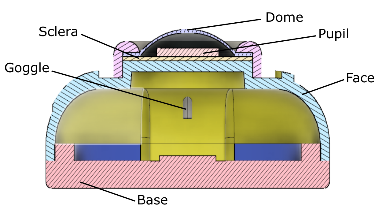
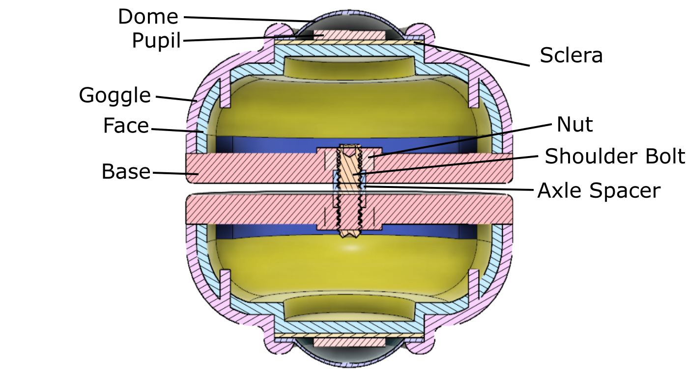
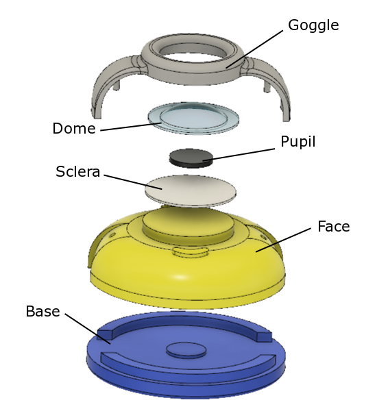
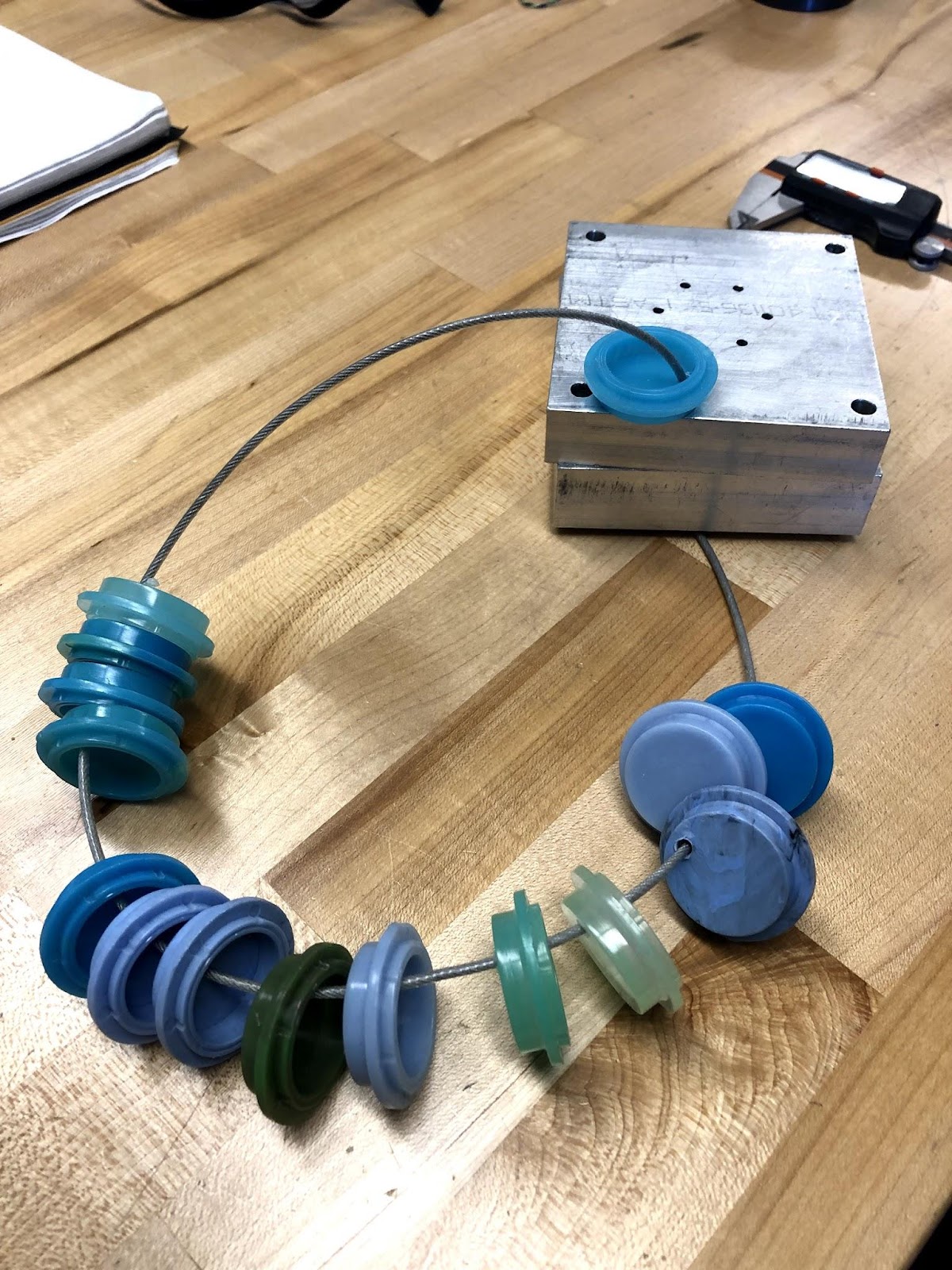
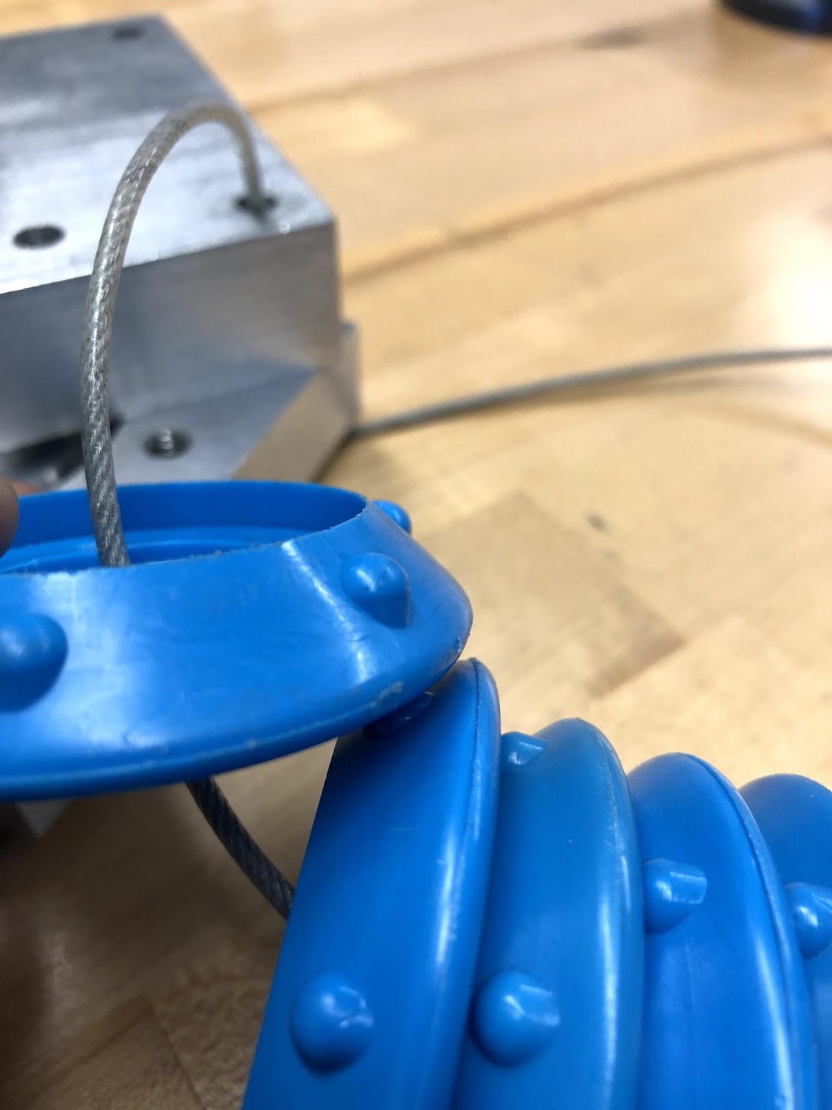
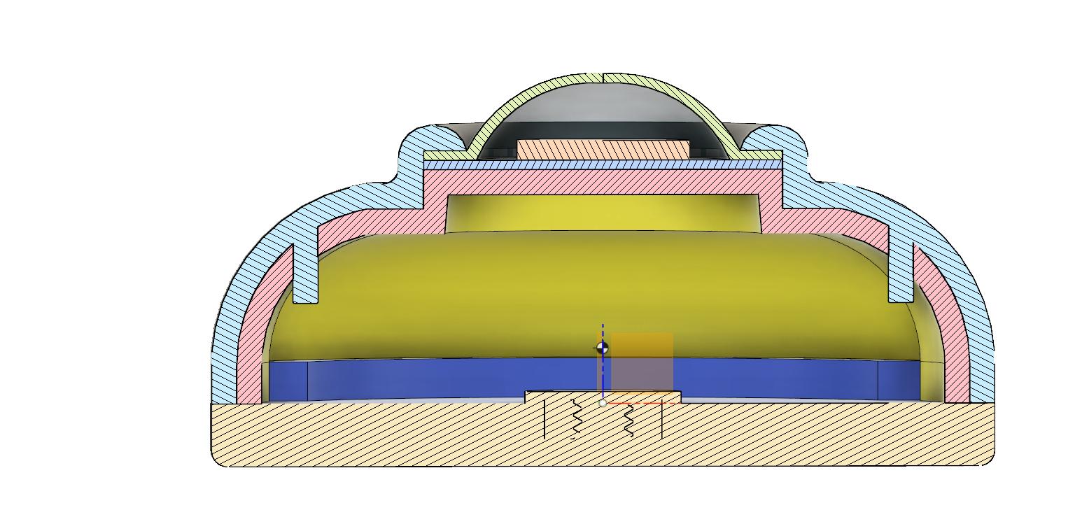
A. Blue Body
Machine & Mold Set-Up: Setting up the Engel for this part was relatively simple. Aside from molding parameters, there was not much deviation from the standard set-up required and detailed in the materials provided. However, fastening the molds to the parts that actually interface with the injection molding clamps presented a few issues. The problems came exclusively with ejectors pins, which were either too short or a bit too long. The pins that ended up being used were the 5.250” pins. These were a bit too short, so the parts that came out had non-negligible places where plastic filled ejector pin holes. There was also quite a bit of trouble getting the ejector pins to align with the mold itself, but we couldn’t tell if this was an issue with the holes or the ejector pins themselves.
Gate Placement: The gate just ran directly into the cavity side of the mold. A simple eyeball estimation is how the runner from the sprue into the mold itself was decided on, as the path chosen looks very close to the shortest path between the two areas. Since the part is largely symmetric, there were no features to avoid, or cosmetic surfaces to protect by placing the gate in a different location.
Injection Molding Parameters: We iterated on multiple configurations of molding parameters, but began with the parameters left on the machine from the last person to use the machine. All parts had a hold time of 8 seconds, and a cooling time of 10 seconds.

Attempts #1 and #2 at injection molding. Short shot and dishing occurred in both of these parts, due to shot size being too small (1.50in), and ejector pins that were too long (5.375”).

Attempt #3. Increased shot size to 1.75in, and shortened ejector pins. There’s less dishing now, but still short shot in the far side (from the mold) of the part
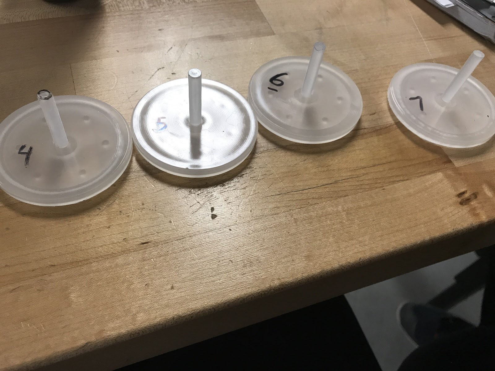
#4 – #8. Changes are just gradual increases in shot size up to 2.30in, and moving the injection boost pressure up to 1800 psi. There is a weldline that still exists at the far side of the part, but since flashing has occurred, we figured the next change must not have to do with the shot size.
#9. Decrease injection speed profile rate.This allowed the injection speed to stay high for longer, which resulted in flashing and burning.

#10 & # 11. Increased injection boost pressure to 2300 psi, and reset the injection speed profile. No more burn, but weldline still present.

#12 – #15. Increased injection pressure profile from 1299 psi – 1650 psi to 1650 psi – 1800 psi. Ran this configuration four times to allow the machine to “catch-up.” Weldline and flashing still present.
Drawbacks: Obvious drawbacks and defects associated with this first run of blue body parts were the flashing and weldline that were created and left unsolved for the time being. Also, another thing that is not necessarily a “drawback” but a “grain-of-salt” observation, is the fact that we did not have any shoulder bolts with our molds. Obviously, this will be a necessary feature in our final parts, so the parameters detailed here may not hold for the final injection mold.
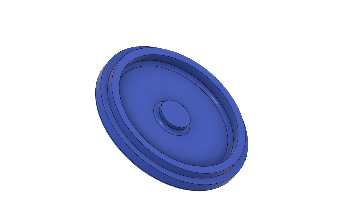
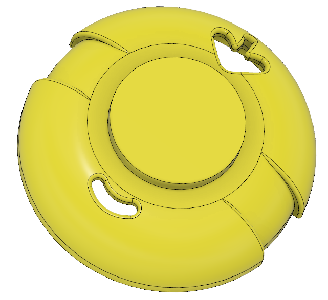
B. Yellow Face
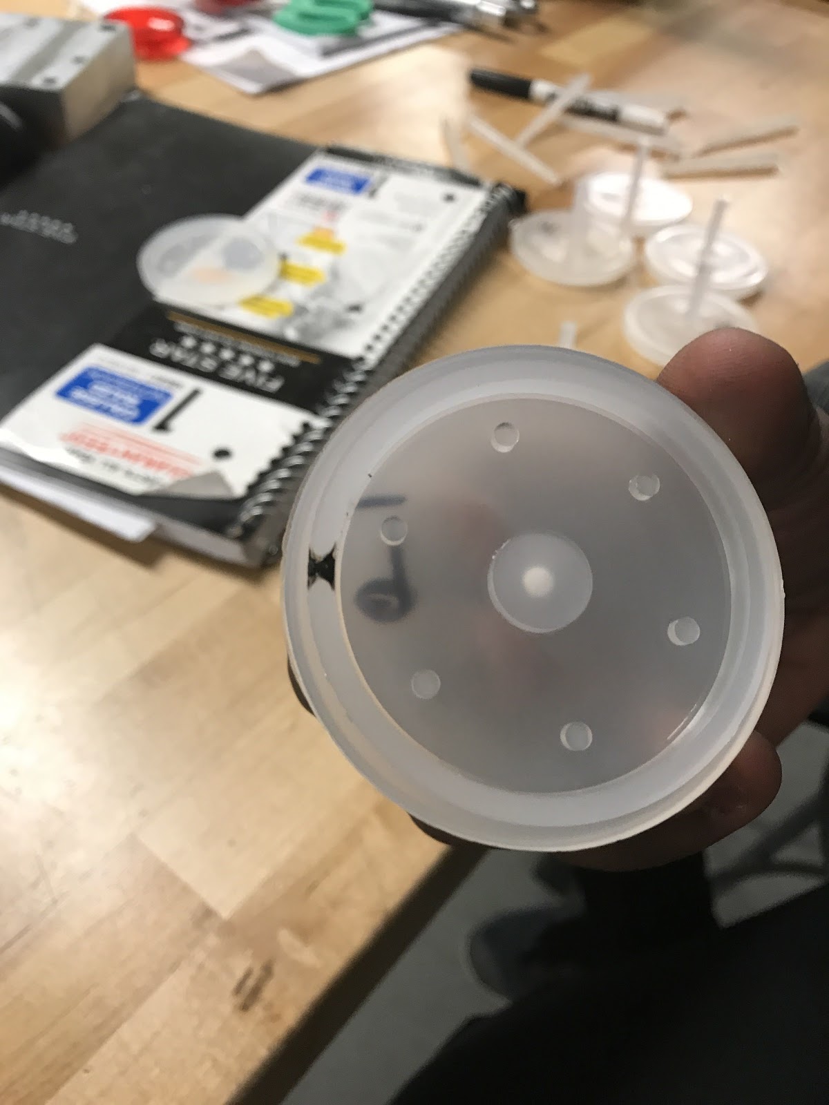
Machine & Mold Set-Up: We needed to use ejector pins closest to 5.353” for the yellow face mold. We decided to use 5.375” ejector pins along with a 0.02” shim to get the ejector pins as close as possible to flush with the part. We reamed the ejector pin holes and did not have difficulty aligning the ejector pins.
Gate Placement: The runner and gate just ran directly into the cavity side of the mold from the sprue since the yellow face part is mostly symmetric and had no features or surfaces to avoid.
Injection Molding Parameters: For our first part we started with a shot size of 2.20” which corresponds to the volume of plastic being injected into the mold. This shot size turned out to be way too large and we has considerable flash on our first part. We then reduced the shot size to 1” which resulted in a short shot. For both of these first two parts we had the hold time set to 10 seconds and the cooling time set to 20 seconds. For the third part we increased the shot size to 1.2” and reduced the cooling time to 10 seconds because the part is relatively thin. This shot size also resulted in a short shot. For our last attempt we increased the shot size to 1.4” which resulted in flash. Moving forward we now know that the holding time of 10 seconds and cooling time of 10 seconds work well and that the shot size will be between 1.2” and 1.4”.
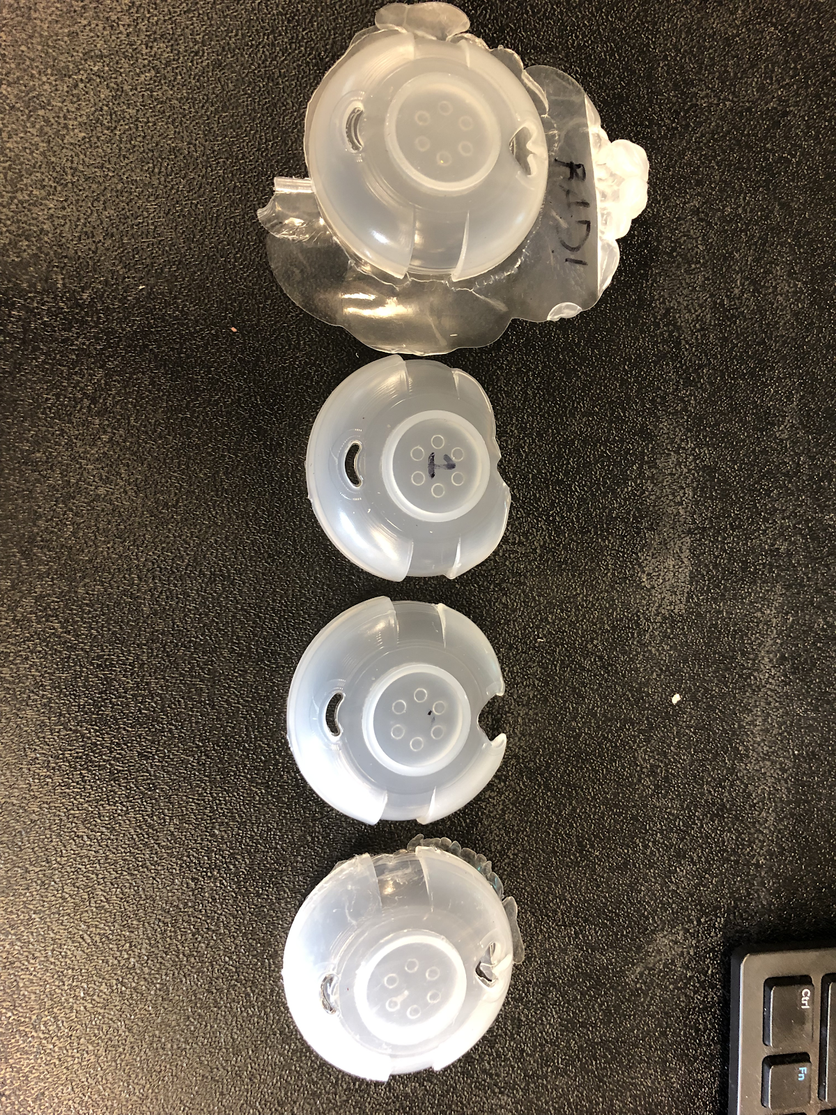
Drawbacks: With the yellow face, the major drawback was the failure of the part to be ejected from the mold. This may be due to the short depth of the sprue hole on the core side of the mold. There may not be enough depth for the plastic to engage with the threads in that hole, so the plastic continually stuck in the cavity side sprue hole. Another problem we saw was that there was a small undercut created by the misalignment of the cavity sprue hole and the hole on the backing plate that interfaces with the clamp. There was quite a bit of overlap between the diameters of those two holes, creating an undercut between the two parts fastened together, preventing the plastic from releasing from the cavity side of the mold.
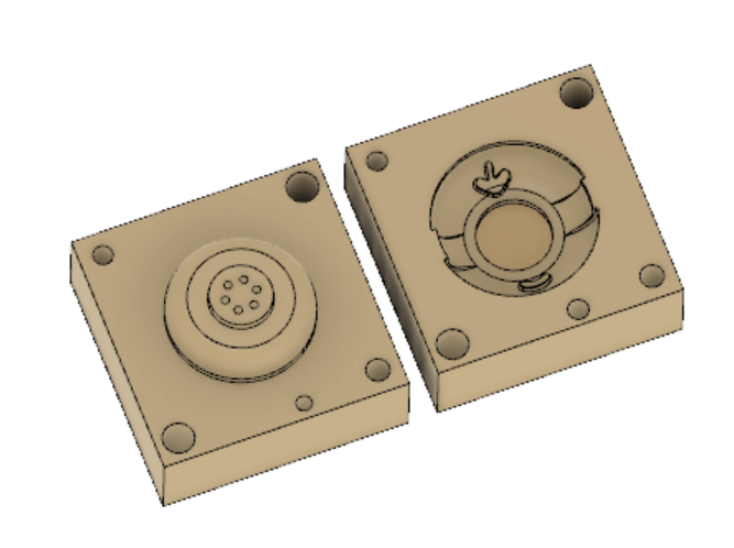
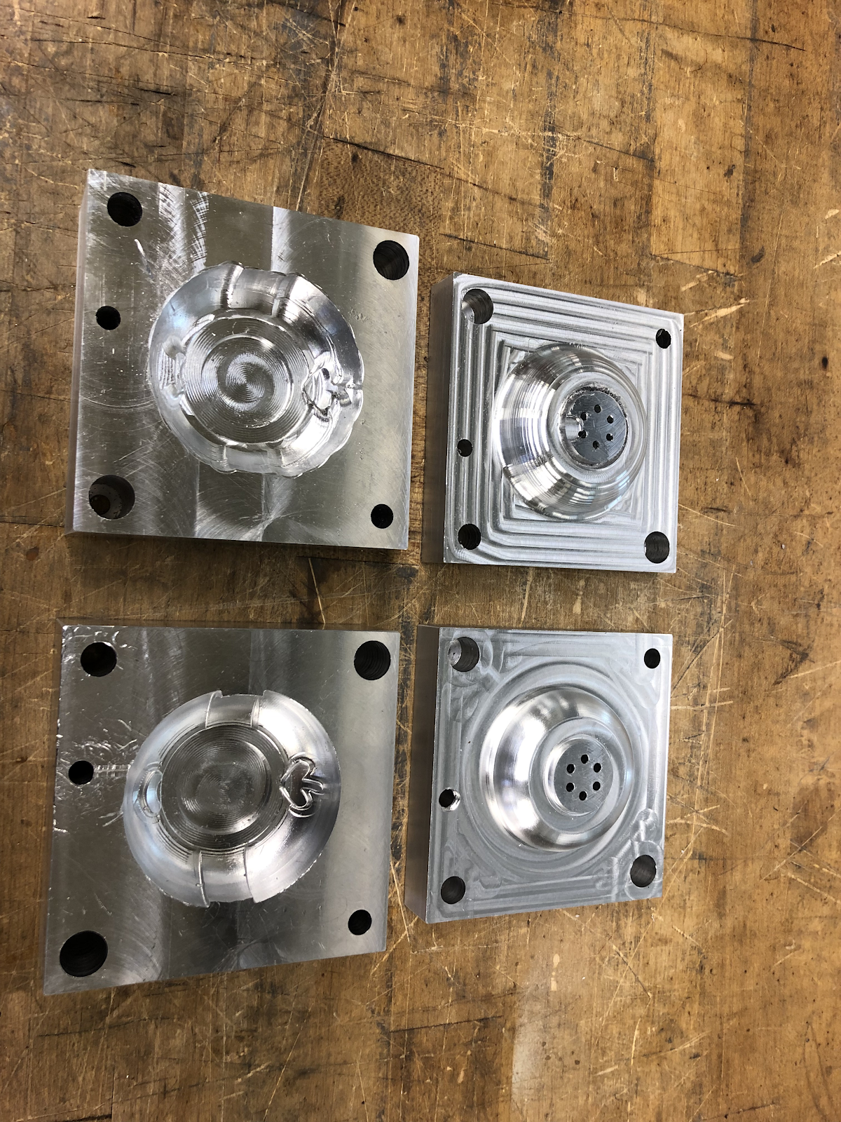
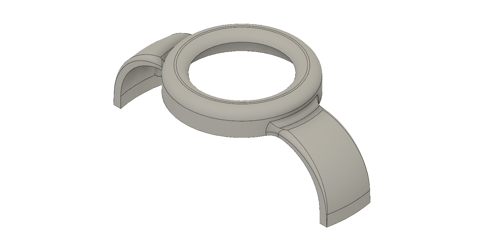
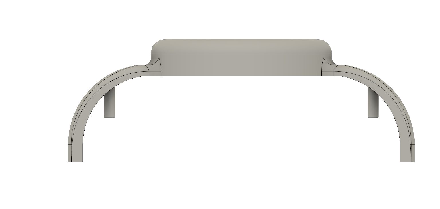
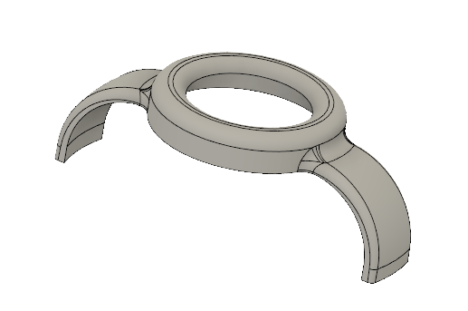
C. Goggle
Machine & Mold Set-Up: Setting up the Engel for this part presented an issue with the mold height. After zeroing the clamp position and finishing the setup for molding, I tried to mold the part by closing the front gate door. However, once I did this, the clamp began to close, but stopped short of meeting flush with the cavity side of the mold. This happened twice in a row. The error message was cleared, and then we simply re-zeroed the clamp position. The clamp closed fully on the third try, but it remains unclear what the reason was for the clamp stopping short of flush with the cavity side of the mold. The ejector pins used for this part were also the 5.250” pins, and they were much easier to align than that of the blue mold.
Gate Placement: The gate runs from the sprue into a runner that traverses around the outer circumference of the goggle mold cavity. This allows both straps at the sides of the goggle to fill first and have plastic meet in the middle. This allows the gate marks to be at the ends of the straps near the base of the yoyo half, minimizing adverse aesthetic effects.
Injection Molding Parameters: Unfortunately, due to ejection mishaps, we were only able to realize 2 goggle parts, where we varied shot size from 1.50in to 1.25in. The other parameters used in injection molding this part were very similar to those used in injection molding the blue part. The injection speed and pressure profiles were identical to that of the blue base. The hold time and cooling time, however, increased from 8 seconds and 10 seconds, respectively, to 10 and 12 seconds. This was not by design, but simply due to the last person to use the machine using the settings. These numbers, especially the cooling time, can definitely decrease. This part will use less plastic than the blue piece, so decreasing the cooling time will increase our production rate. Again, major flashing still occurred in the 1.25 in shot size configuration, but the issues with plastic getting stuck in the machine made it extremely time intensive to iterate through the different shot sizes and other parameters.
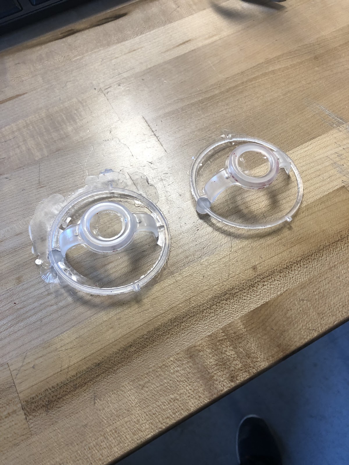
Drawbacks: The major flashing is the most noticeable defect in the goggle part that must be addressed in future iterative processes with the injection molding parameters. However, one of the major features hindering our progress was the failure of the sprue plastic to eject with the rest of the part. When the molds are both clear, the part fills and ejects perfectly fine, but the plastic in the mold cavity sprue hole stays behind. As a result, any molding you try to do immediately after this fails due to plastic not being able to fill the mold because of solid plastic stuck in the sprue hole. Initial hypotheses suggest that it may either be undercutting between the mold and the mold backing part like in the yellow face part. Alternatively, it can be plastic not fully engaging with threads in the core side of the mold, or the sprue ejector pin being too long for the core sprue hole. There was a lot of aluminum cleared from the core side of the mold, so maybe there isn’t enough depth in the hole before the ejector pin fills it.